So I have some motion-sensitive lights in my car hole, and I got the idea in my head that I wanted to modify them.
You see, motion-sensitive lights are nice in that they turn on when they see you, and turn off when they don't. This is great if you happen to need their illumination when you're in the sensor's field of view, and also great if you don't need your light when you're out of the sensor's field of view.
It's not so great if you need their light when you're out of the sensor's field of view.
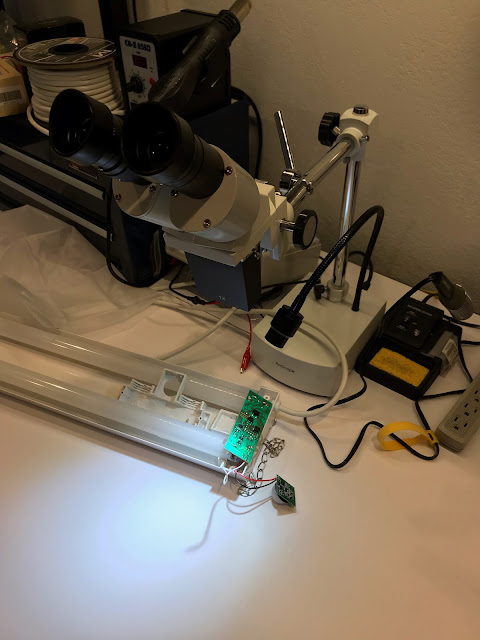
So over the weekend I cracked open one of the lights to suss out how it works and see if I could hack it a little to make it more suitable for my needs. My first thought was to simply install a switch that would bypass the PIR sensor, but when I got inside I noticed that the control wire from the PIR (passive infra-red) board was marked "PWM", which rather implied that the driver board was capable of dimming and not just switching on and off.
Now PWM usually (we'll get back to this in a minute) stands for "pulse-width modulation", which is basically a way of switching something on and off really fast so that the observed output averages out to some level between all the way on and all the way off.
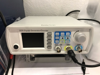
So I got myself a waveform generator, set the output to a pulse with 30% duty cycle, and hooked it up in place of the PIR board on the PWM line.
The result: yikes. The light flickered horribly and just misbehaved in all the worst and most nauseating ways. Ok, that's no good.
I messed around a bit more, trying different frequencies, different duty cycles and so on without much luck. Then, out of boredom more than anything, I tried feeding it a sine wave at a really low frequency, and to my great amusement the light started ramping up and down smoothly!
So it wasn't actually PWM after all, it was an analog input. They just called it PWM. For reasons, I guess.
Setting aside my waveform generator, I instead grabbed my bench power supply and set it to output an intermediate voltage, and hooked that up. This resulted in a very nicely dimmed light. I played around a bit more with different voltages, and then ran into a problem.
The light wasn't going to full brightness anymore, nor was it turning off when the PWM input was disconnected.
After a bit of debugging, I found the culprit. Every electronics hobbyist's sworn enemy: the tiny surface-mount mosfet.
This didn't look quite as bad before I desoldered it, but it was indeed the culprit.
You see, mosfets, especially tiny little ones, are rather susceptible to voltage spikes on their gate pin. When I had been poking at its gate (which is hooked directly to the PWM line) with the waveform generator, I had clipped the ground pin to the board ground and clipped the signal lead to the PWM line. However, when I switched to playing around with the power supply, I had clipped the positive supply to the PWM line and simply touched the ground lead to the board ground, since the alligator clips on the power supply were much larger than the ones on the waveform generator and I was worried about them slipping and shorting something out.
As a result, this meant that when I removed the ground lead, a fairly large floating voltage was presented to the mosfet gate, which unfortunately cooked it.
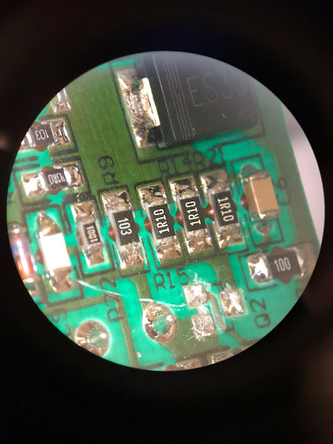
Anyway, you can see where it's meant to be on the board here.
It goes on the empty pads above the Q2 silkscreened text.
To give you a sense of scale, here's my index finger.
Thankfully I was able to read the part number off the mosfet, and I put in an order to Digikey for a replacement, which cost 44¢.
Which is to say I ordered 10 of them, because I'll probably screw up one or two trying to solder it back into place. I then kept filling my cart with stuff I might need at some point in the future until I got to about $50 of crap because, unlike Amazon, Digikey charges $7 for shipping and I'm not going to spend $7.44 for a 44¢ part.


