This right here is a Yamaha Reface DX. It's modelled after their classic line of Digital FM synths from the 80s and 90s, with the DX7 being perhaps the most famous and widely used synth.

This one has a problem, though. Some of the front panel switches don't work, and some of the LEDs don't light up.
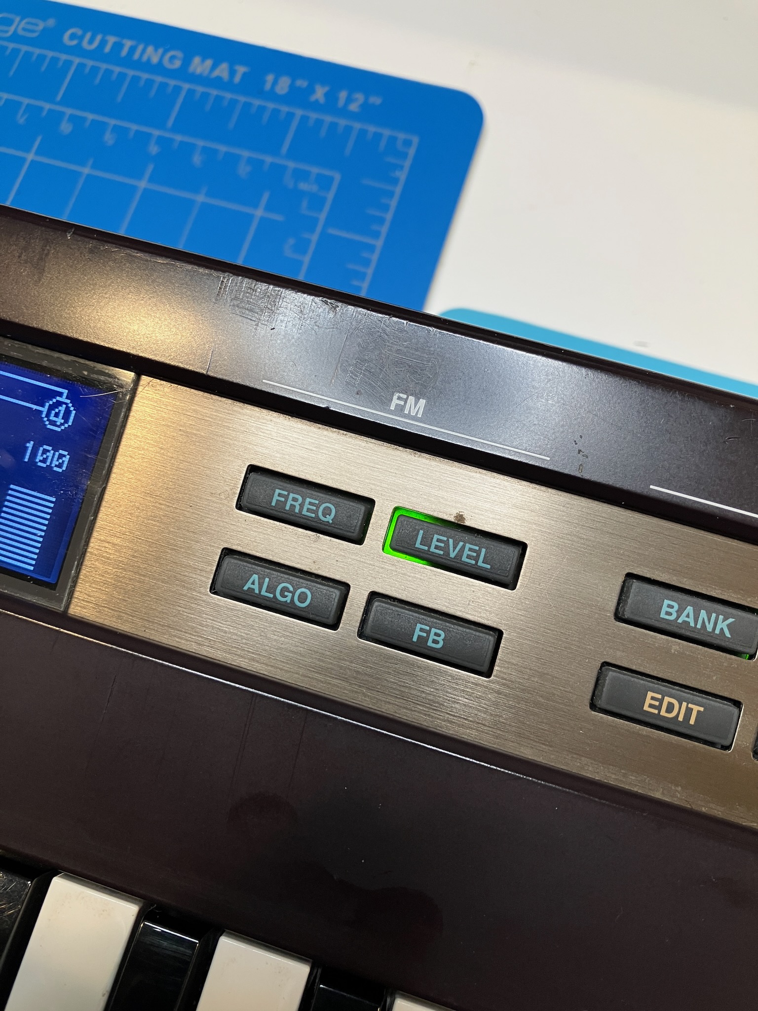
For example, here's the LED behind the FREQ button lighting up as it should:

And here's the LED behind the LEVEL button doing a whole lot of nothing:

Oh and also it doesn't make any sound. I guess that's important too.
Now one of the problems with these compact synths is that because of their small size, people often tend to treat them like those old toy synths, even though, well...

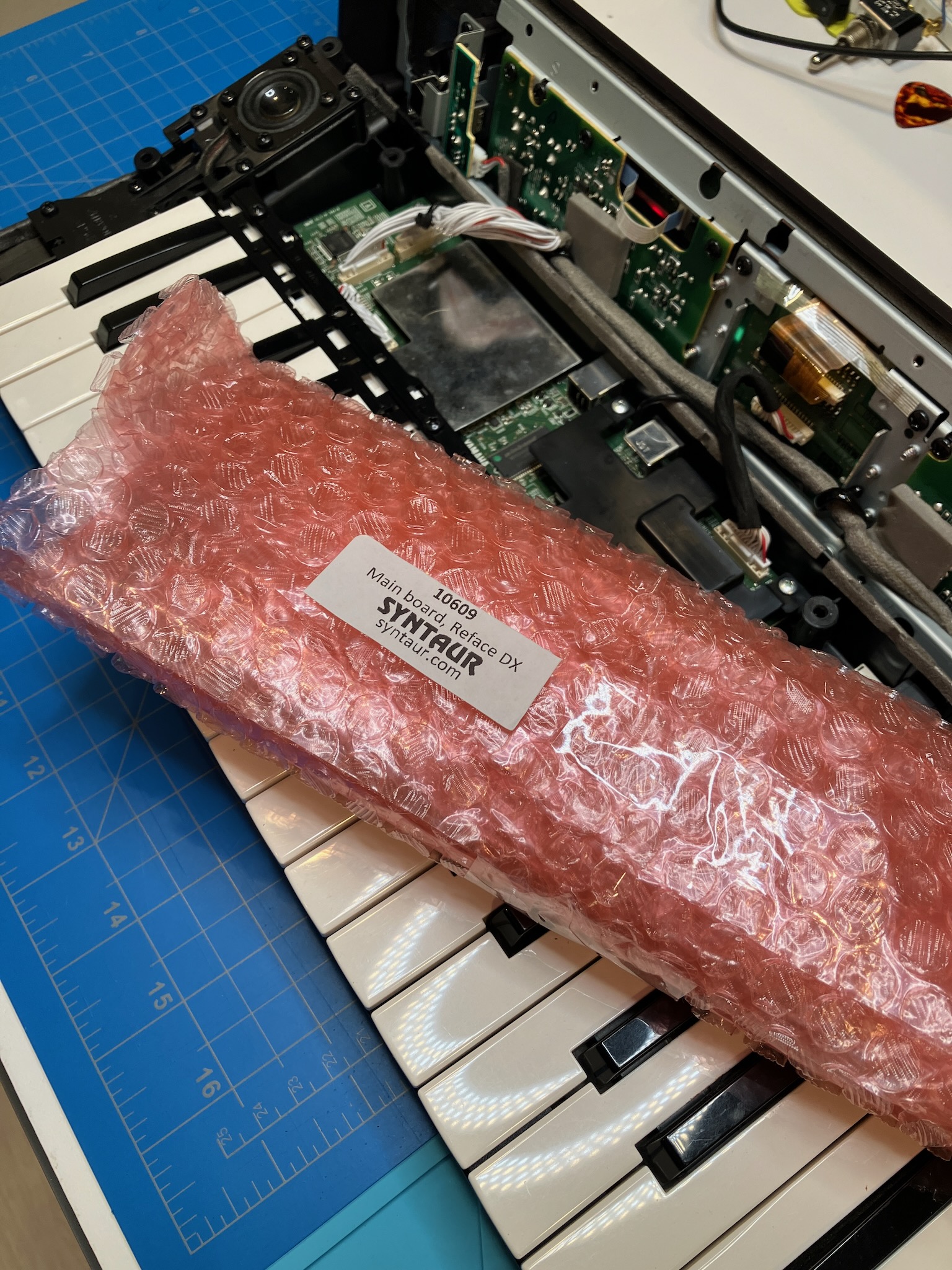
But thankfully I didn't have to pay $500 for this one. Anyway, let's crack it open and see what's inside.

And interestingly there's more in here than I thought there might be. These days you can run a synth like this on a board the size of your thumbnail (not the chip, but the whole board) but I guess the Yamaha engineers decided to fill the space available to them. No harm done I suppose.
So over here on the left side is the chip that drives the switch and LED matrix.

If we probe one of the matrix lines with the scope, we can see it scanning.

But if we probe another line next to it, we see something that looks almost like a flat line...

However, if we bring up the vertical scale a bit.

We can see that it's still trying to strobe the lines, but it's lost its pull-down resistor.
Now I could dig into this board and try to figure out which resistor is faulty, or trace down a broken via, but I really don't feel like it when replacement mainboards are still readily available.
Though at $150 they're not especially cheap, but given the bargain I got on the synth I'm still coming in under budget.
Now to get to the mainboard we have to remove the keys.

And the keybed PCB.

And then to get the mainboard out we of course need a different size screwdriver.

But once we've got those screws removed, the mainboard just lifts right out.

And then the new mainboard goes in, after we've removed the curious bits of kapton tape that were stuck to each connector.

And we can verify that the switches are working and the previously "dead" LEDs have come back to life.
But the synth still isn't making noise, curiously, so let's check the volume slider.

If we measure the resistance on the wiper for the octave slider next to it, we get a reasonable reading:

But unfortunately the volume slider is being rather unreasonable.

And after spraying it with a little contact cleaner...

It's somehow still not working. Lovely.
Just to test things out, let's try jumpering the volume slider with a fixed resistance.

And if we test the resistance now, we see a much different result.

But unfortunately the synth still doesn't make noise. Because I put the resistor on the wrong pin, it should have been like this.

And now the synth makes sound. Good. So we can order up a volume pot, and let's just go ahead and replace the octave pot too since it was reading a bit funny on one end.

We just have to pull out this front panel sub-board.

And do a bit of desoldering. Using a hot air gun can really help with larger mechanical solder joints like these two tabs in the middle.

And with a little magical slurp from my solder sucker, both pots come out easily.

Goodbye old slider pots, you left us too soon.

Then the new pots get soldered in.

And all that's left to do is reassemble.

But there's still some finishing touches left.

Like replacing the missing rubber foot.

And getting rid of the Alkaline batteries before they leak and destroy everything.

And with all that done, we're back in business.

And ready to make some sweet 80s synth-pop!
1 comment:
All of that tinkering just to enable 80s synth pop? I'm not sure you thought this project through all the way to the end...
All the same, impressive job from someone that is electronically illiterate.
Post a Comment